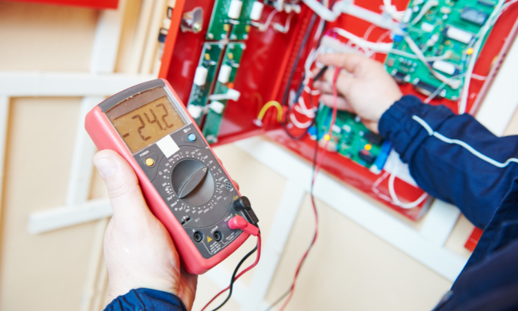
The earth resistance tester measures the earth resistance of an earth grounding installation such as those used in computer server rooms, military installations, cell phone sites, radio towers, etc. This test is to determine if the ground is an efficient conductor of electricity.
The conductivity of the ground depends upon the soil type. For example, if it's rocky ground, then earth mats or counterpoise earth wires could be buried to lower the resistance and reduce the effect of the lightning strike.
In order to achieve effective earthing of electrical systems, soil resistivity must be adequate. Few features of an earth resistance tester are quite similar to the environmental meter 5 in 1, like measuring humidity. Environmental meters are an instrument which can measure humidity, temperature, and sound.
We will be discussing the three basic test methods of an earth resistance tester in this blog post
- Fall of potential method
- Dead earth method
- Clamp-on test method
Fall-Of-Potential Method
The fall-of-potential method is the most common way to measure earth electrode resistance. This system is based on IEEE standards and is suitable for transmission line structures. Experts use two electrically independent test electrodes in this method. Electrically independent electrodes are (P) potential and (C) current. If you are measuring large electrode systems, you need to use special procedures. Below are the three main methods to test earth resistance under this method.
- Four Point Method: The resistance curve plotted after a number of tests are done at different spaces of a Potential Probe "P" to determine the full fall of potential. It is also known as the Wenner Method.
- Three Terminal Method: An alternative method is to take three measurements at a defined distance from a Potential Probe "P" and calculate the resistance using mathematical calculations.
- 68.1% Method: The 8% Rule specifies that each measurement is made with Potential Probe "P" at a distance of 68.1% between the electrodes.
There are three points of ground contact: an earth electrode, a current probe, and a voltage probe. Thus, the earth electrode on the tower footing is injected with current by the digital earth resistance testers. The outer electrode (C) passes an alternating current (I), and the inner electrode (P) measures the voltage at an intermediary point between the outer and inner electrodes. From the earth, current flows to the remote current probe and then back to the tester. A voltage drop results from this current flow. Voltage drops are proportional to the amount of current flowing and the resistance of the earth electrode.
Dead Earth Method
It is the simplest method for testing earth resistance. The method measures the resistance of two electrodes in series- the driven rod and the water system.
When you use a four-terminal instrument, ensure to connect P1 and C1 terminals to the earth electrode, and P2 and C2 terminals to an all-metal water pipe system. Connect the earth electrode to X, the pipe system to P, and the pipe system to C with a three-terminal instrument. The resistance of an extensive water system should be only a fraction of an ohm. In this case, you can interpret the instrument reading as representing the electrode resistance.
Clamp-On Method
Ground meters perform a stakeless test, which is an earth resistance test without disconnecting the ground. The stakeless test involves:
- Applying a known voltage to a loop circuit that includes ground.
- Measuring current flow.
- Calculating the loop resistance of the circuit.
Testers with four poles may also perform stakeless tests. Nevertheless, they use a voltage clamp and a current clamp and keep them separate to avoid interference. An operator must make sure that the earth is included in the return and be aware that the tester will measure the complete resistance of the path. Loop elements are all measured in series. When the ground resistance is higher than the effective return loop resistance, it results in low return path resistance.
Final Words
Earth resistance testers are useful for measuring the earth's resistance. Using the tester, you can measure the earth's resistance using three different methods, and this blog gives a brief description of all the testing methods. They use a hand-operated generator that consists of two principal components. Earth testers primarily consist of a rectifier and rotational current reverser. AC is converted to DC through a rectifier.
Those testing on Earth should work only on DC. A tester also has two commutators besides the current reverser and the rectifier. Each commutator has four brushes. Resistance testers allow engineers to skip a lot of work by telling them exactly what voltage or current to focus on.


